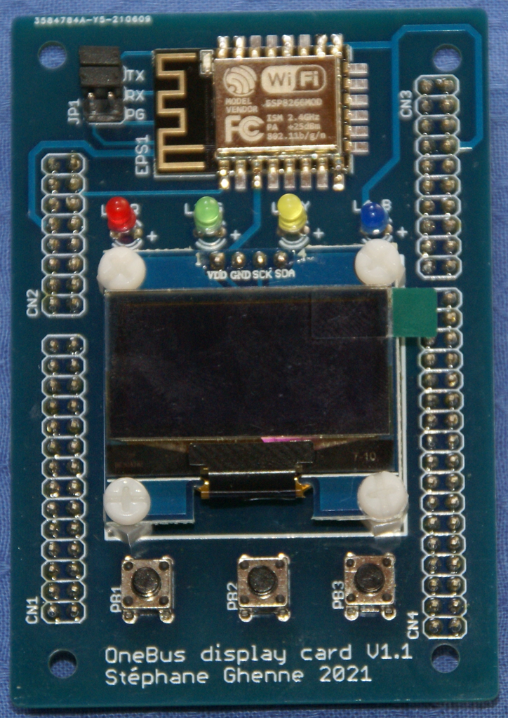
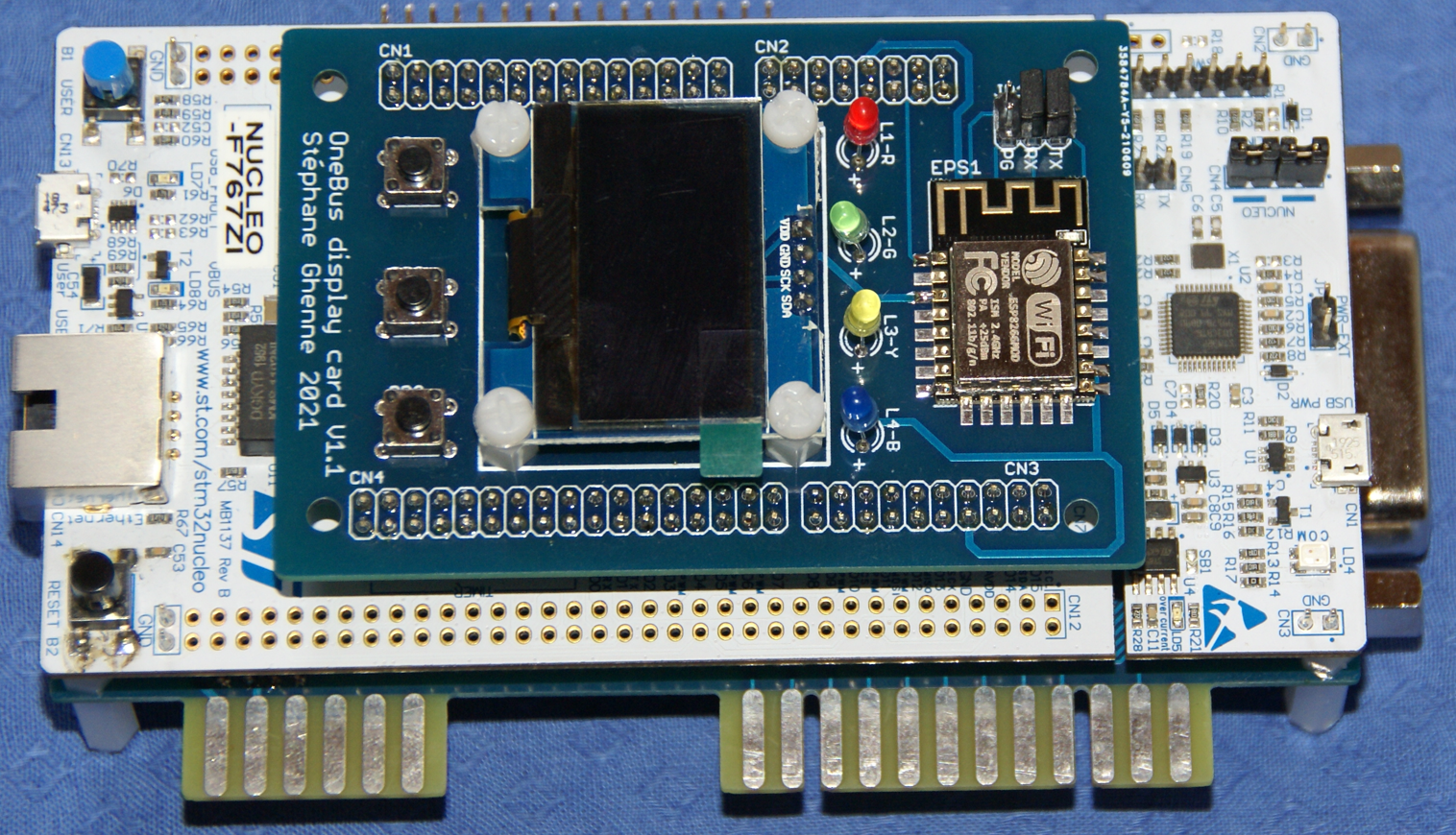
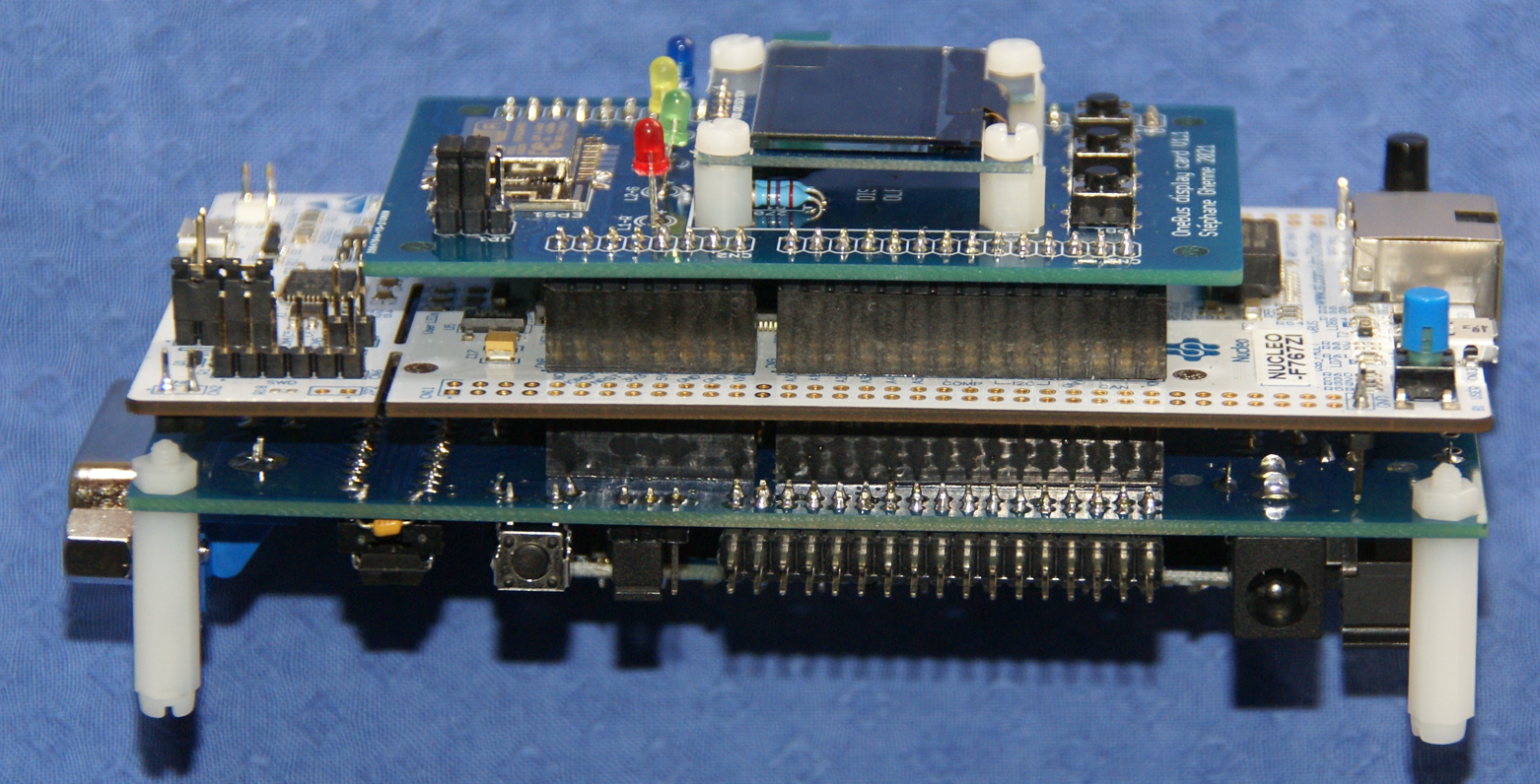
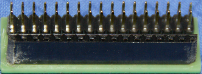
Once you have procured the display and connector board pcb's, the next step is to solder the different components on the boards.
Below you can find the bill of materials of each and a picture showing the position of every component.
Lastly the two boards are secured to the Nucleo F767ZI board.
The OneBus is powered with a DC jack connector.
When everything is soldered and assembled to the Nucleo board, you need to flash the OneBus.
Be careful to respect the direction and the color of the leds L1-R, L2-G, L3-Y and L4-B.
Note the setting of jumper JP1. This jumper is used to update the ESP8266 Wifi card. In normal use Rx and Tx must be closed.
Be careful to respect the direction of IC1, IC2, IC3, LS1, LS2, LS3, LS4, LS5, LS6, LS7, LS8 and LS9.
The setting of JP1 depends on the used power supply. This is further explained below in the Power supply section.
Paddle to connect TED computers to the OneBus.
Also compatible with the 1551 disk drive.
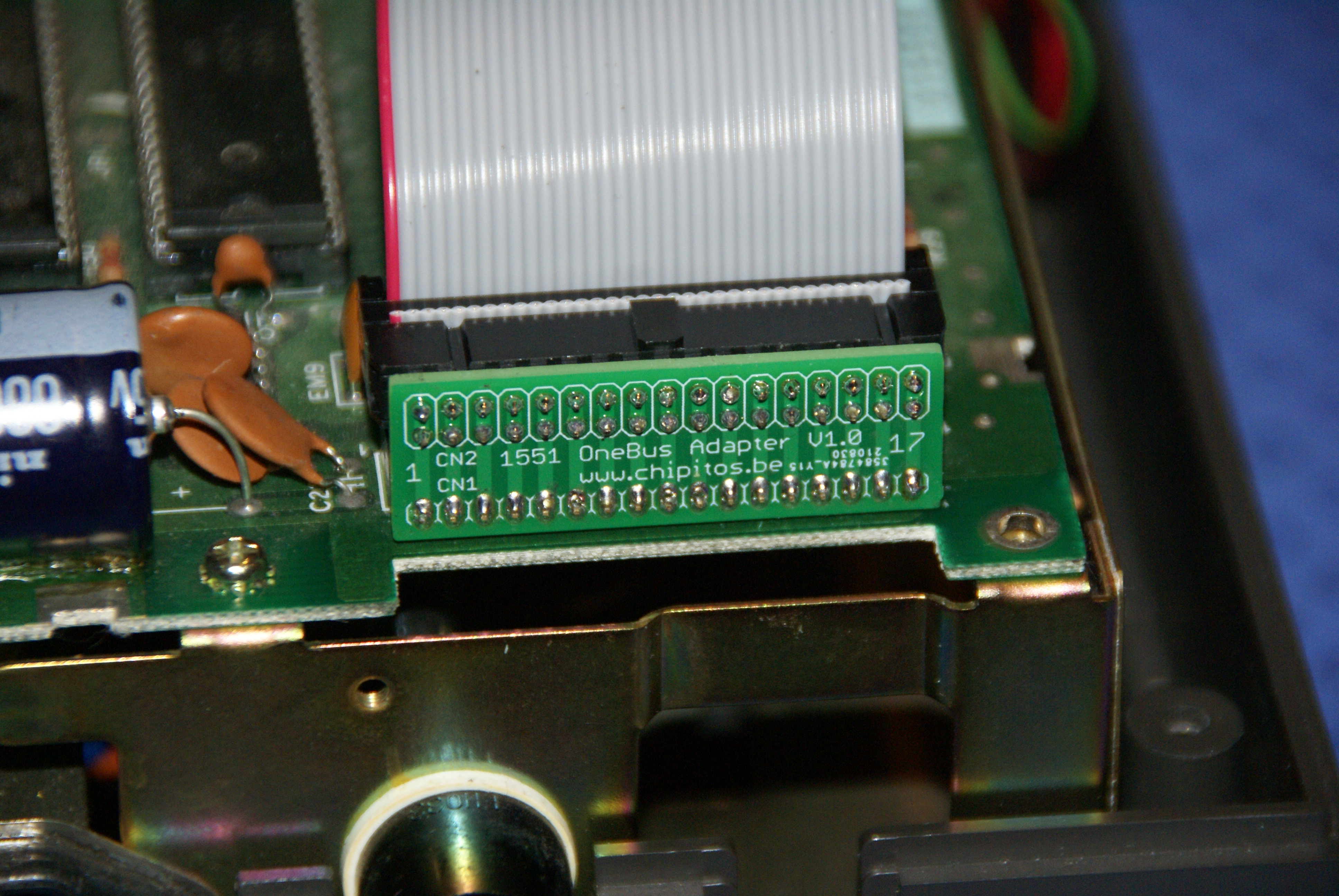
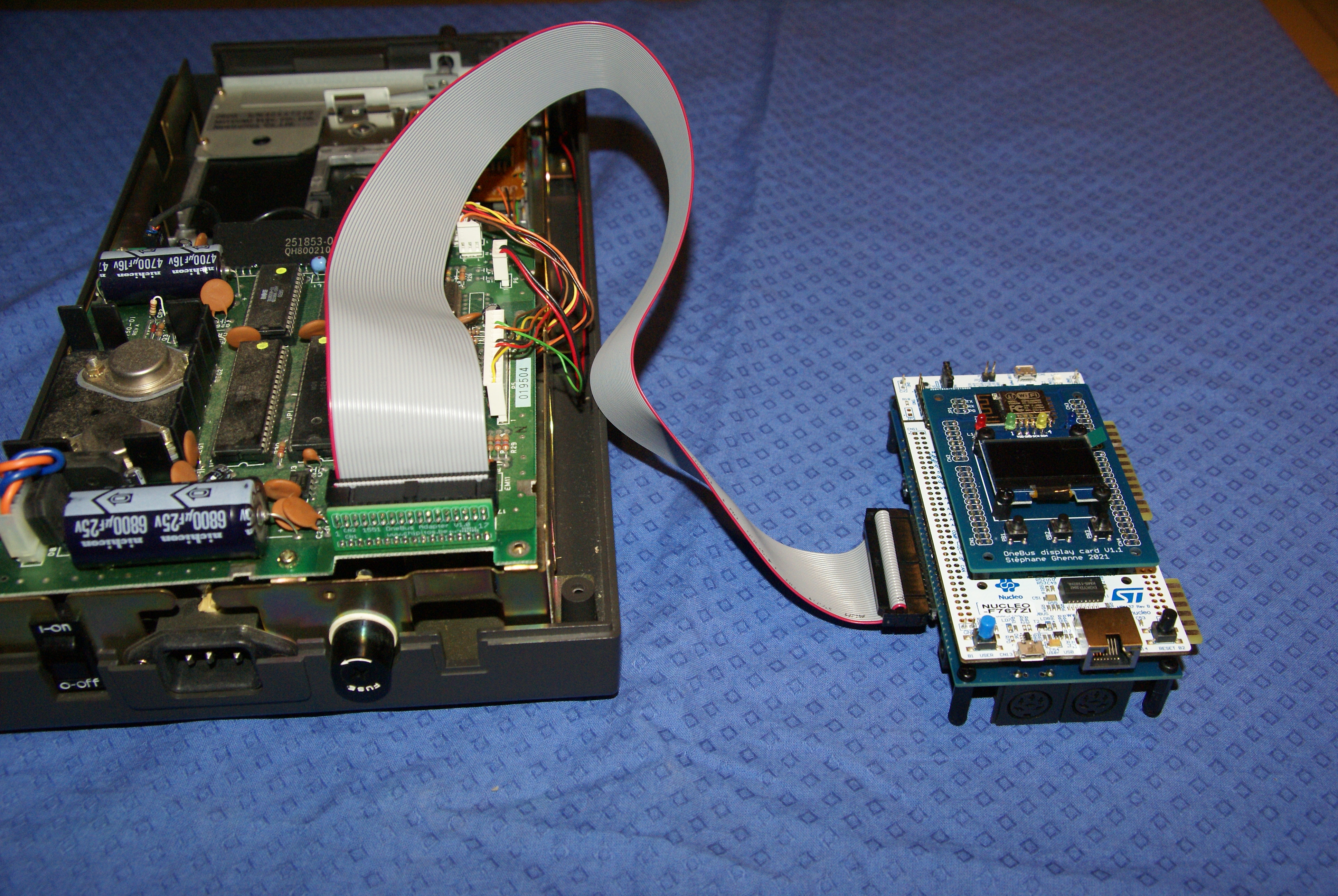
Adapter to connect à 1551 disk drive to the OneBus or to connect the 1551 to the OneBus paddle
The OneBus is powered with a DC jack connector with following characteristics:
-
- External connector: GND | 5.5 mm diameter.
- Center connector: +VDC | 2.5 mm diameter.
The JP3 jumper of the Nucleo board must be set to position VIN, whatever the voltage of the power supply
On the OneBus connector board, the JP1 jumper must be place in:
-
- 5V position if the power supply is 5VDC (recommended)
- VIN position if the power supply is between 6 and 9VDC

